
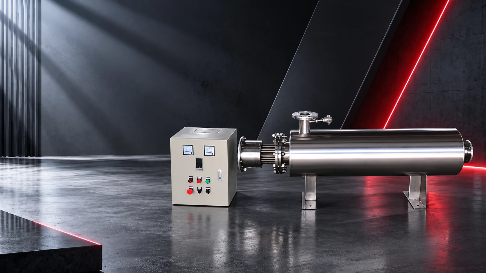
01Why gas duty is easy to get wrong
Heat capacity per cubic metre
Air at standard conditions carries about 1.3 kJ per Nm³ per °C, nitrogen about 1.2, argon about 0.66. Steam at atmospheric pressure carries several times more per Nm³. Sizing by volume without the density is where the error starts.
Mass flow first
Convert Nm³/h to kg/h using the gas density (nitrogen 1.16, argon 1.78, air 1.29 kg/Nm³), then apply kW = ṁ × cp × ΔT ÷ 3,600. At pressure, use the actual pressure-corrected mass flow, not the free-air figure.
Small kW, hot sheath
A 40 Nm³/h nitrogen heater raising the gas 200°C needs only about 2.9 kW. All of that heat still leaves through a small tube surface in a gas that is a poor collector of it, so the watt density and the velocity do the real work.
Turndown
Gas systems are often run at 20% flow during idle periods. A bank that is safe at full flow is a dry-fire heater at idle flow unless the steps are arranged to cut in with the flow.
The one-sentence design rule: for gas, the danger is never the total kW, it is the ratio of kW to the mass of gas actually passing the element at that moment.
02Worked sizing, nitrogen superheat
Duty
400 Nm³/h of nitrogen, 20°C to 350°C. Mass flow 400 × 1.16 = 464 kg/h; kW = 464 × 1.04 × 330 ÷ 3,600 ≈ 44 kW before losses and efficiency.
Element area
At 2 W/cm² the 44 kW bank needs roughly 22,000 cm² of heated surface — about 19 m of Ø16 mm tube. That is what forces a long, multi-pass vessel rather than a short bundle.
Velocity
Gas-side velocity through the heated section should stay in the 5-15 m/s band for a clean, dry gas. Below that, the boundary layer thickens and the sheath temperature climbs even though the duty is unchanged.
Pressure effect
The same mass flow at 6 bar occupies a fifth of the volume, so the velocity collapses unless the tube bundle is redesigned. Pressurised gas is the classic case where a heater sized on atmospheric flow runs hot.
All four numbers move together. Change the outlet temperature and the area requirement changes; change the pressure and the velocity changes. This is why a gas heater is quoted from a data sheet, never from a kW figure alone.
03Construction choices
Sheath material
Incoloy 800 or 840 is the default above about 400°C sheath temperature; 304/316L is fine below it for dry gas. Moisture or halides change the answer completely.
Internal versus external flow
Gas inside the tubes with the elements around it gives predictable velocity and easy element replacement. Gas across an element bundle is cheaper to build and harder to keep at velocity in every pass.
Insulation and shell
A 350°C gas heater loses a meaningful fraction of its duty through a bare shell. The lagging is part of the efficiency figure, and the shell temperature is a personnel-protection question.
High-temperature seals
Flange faces and penetration seals leak at hot service long before they leak cold. Specify the gasket for the operating temperature, and record the hot re-torque in the commissioning notes.
For inert gas blanketing or purge duty, where flow is small and intermittent, a low-watt-density band with a hard airflow interlock is safer than a compact high-output unit.
04Controls and protection
Gas has almost no thermal inertia. A 40 kW bank feeding a small bore line can move the outlet temperature tens of degrees in a second, which means the control loop must be faster than the process, not merely accurate.
Minimum protection set: airflow or flow proof before energisation, an overheat cut-out on the element outlet that is independent of the controller, and a low-flow trip that follows the compressor or the valve that actually fails.
If the gas can be interrupted — a closed valve, a filter change, a compressor stop — the interlock must be wired so that the interruption removes power, not just the alarm.